Saturday, March 16, 2013

Getting back into the blog (and the cockpit well grate)


Tensie Mae's cockpit well grating rigged for use as a table
Well it's been almost two years since I posted here. I've done a lot of work on Talofa Lee but have found I am usually too tired after working on her to get on the computer and post.  I also took a full time post as science teacher at a local high school for 2011-2012 when the school was unable to find a teacher.  The out-of-classroom work teachers do is extensive (at least it was for me) - preparing for lectures and demonstrations and labs and grading papers.  So that's all of my excuses for not posting.

I have Talofa Lee about 80 percent ready for launch other than cosmetic work on the interior and exterior wood.  I have completed a variety of large projects and will make a few posts later to highlight some of them.

Oh there's one more excuse - I haven't done much on her this winter because of other projects (including gutting and renovating a bathroom in our house). 

This week I spent a few hours at the barn working on Talofa Lee to try to get back into a routine that will lead to finishing her.  I decided to build the long-planned cockpit well grate to replace her original grate that was very worn and rickety while I consider my plan for doing the more important systems completion. 

The grate is a well designed feature of the boat.  It is made of teak and sits in the bottom of the well and provides good footing while allowing drainage through the grate into the cockpit well drains.  If desired it can be moved to the top of the well to sit on rails and make the cockpit well flush with the seats so the cockpit can be used as a sleeping area.  I also made a support for the grating on my other boat - Tensie Mae - so I can use the grate as a cockpit table (see the photo at the top of this entry).

As I said Talofa Lee's grate and well were in poor shape and needed a lot of TLC and a new grate.

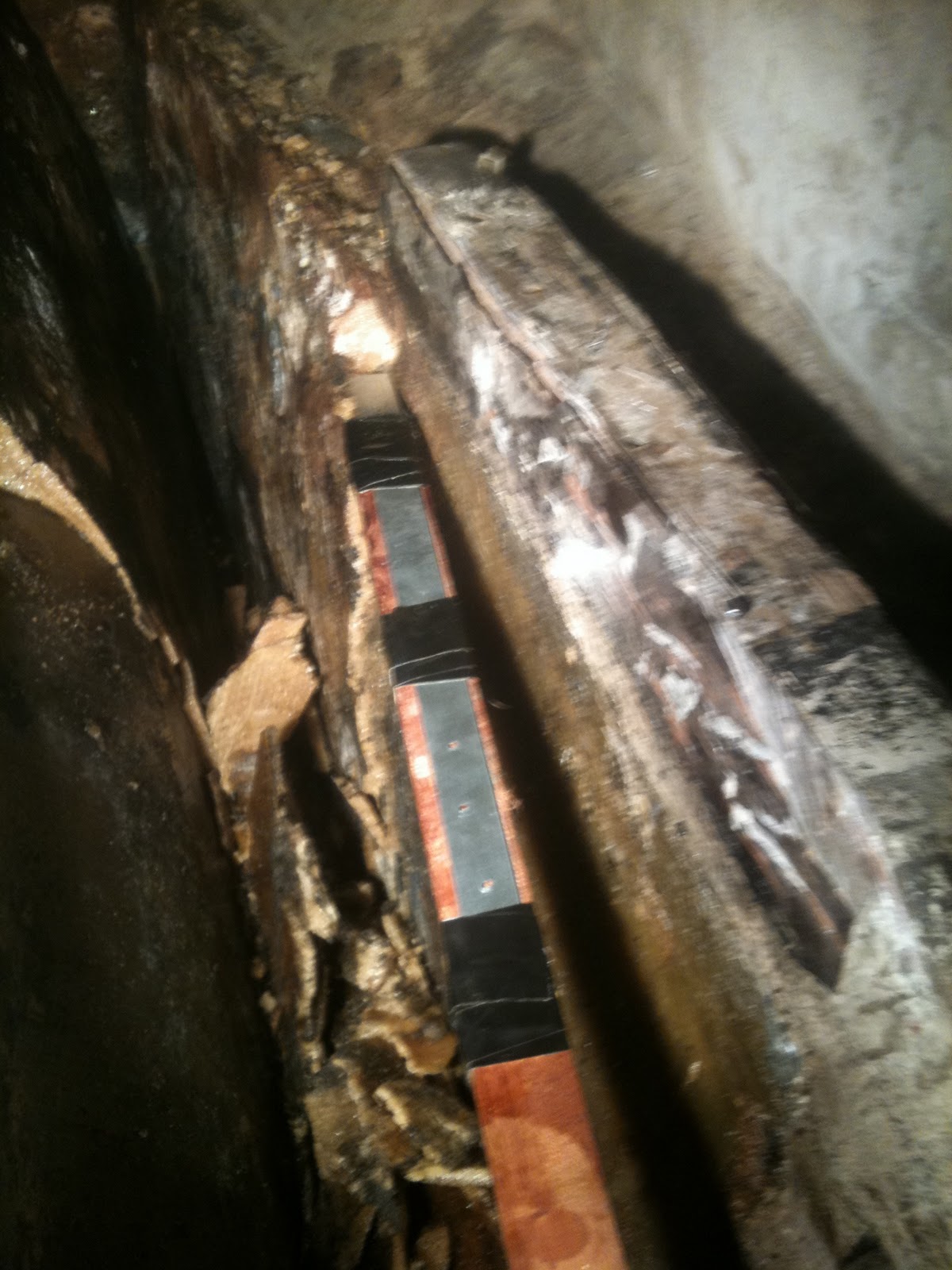
Talofa Lee's cockpit well and rails for grate

The old grate was intact but was badly worn. Many of the screw tips were exposed on the upper surface of the grate due to the wood being worn.

Talofa Lee's cockpit well grate

The grate is a matrix of half-lap one inch square stock held in a picture frame of one and a quarter inch thick stock rabbeted to accept the matrix.


Talofa Lee's cockpit well grate

The matrix is screwed together at each half lap using 3/4 inch long flat head SS screws.  I disassembled the old grate and used the hardware in the new grate.  Only one screw was damaged in disassembly and I replaced that one.

I built the new grate out of Spanish cedar rather than teak.  I used the cedar for two reasons- one is that I had never built a grate like this before and if I messed it up using the cedar would minimize my costs; and the second is that the cedar should weather and wear well enough and look good enough so I can use it for a few years and - since I would have the experience of having built one before - I could build one out of teak when the cedar became worn.

The best method for preparing the matrix is to cut all the dadoes for the half laps at once (or as limited by the width of your wood) then rip the matrix strips from the wider board.  That's what I did using my table saw and a wobble dado blade. The dadoes are a half inch deep.  The open areas are an inch and a half wide.  The strips are one inch wide.

Spanish cedar board dadoed and ready for ripping

After the strips are ripped it's pretty simple to put the matrix together.  I had to do some sanding of the completed matrix because my dado depth was just a little bit too shallow.

Assembled grate matrix

After assembly I trimmed the edges straight and measured to get the width of the picture frame surround.
Completed cockpit well grate

Then I cut and rabbeted and installed the frame then used a quarter inch roundover bit in my router to round the edges on the top; and used a microshave plane to take the corner off the bottom edge. A test fit on the rails in the cockpit well and inside the well confirmed that it was ready to go to work.  I stood on it and it passed that test
.

Two coats of 50/50 varnish and mineral spirits have been applied.  It is now waiting for completion of the rest of my projects and sea trials - in April???

I'm happy with the results.


Saturday, April 9, 2011

Cabin top handrails, postscript

I meant to include this photo in the last post on cabin top handrails.
If bronze machine bolts are used to install the handrails, and you see discoloration like this at the handrail attachment point, the bolt has corroded badly and the handrail is unsafe for use.

Cabin top handrails

Cabin top handrails are a classic feature on many sailboats, including Talofa Lee. The looped rails along the cabin top allow some security when moving along the deck and onto the cabin top.  Made of teak, and through bolted through the cabin top with bronze machine bolts, they can be pretty, strong, and useful.

However, as I found out on Tensie Mae, the rails are prone to leak at many of the bolt locations where the rail loop meets the cabin top.  When leakage occurs, the bronze bolts corrode, wasting the bolt where it can't be inspected without removing the rail.  On both Tensie Mae and Talofa Lee, many of the bolts had completely wasted away, or were so thin that their strength was minimal. Reliance on these handrails under these conditions could have resulted in a fall or a man overboard.

I decided to forego the classic look of the rails on Talofa Lee. Perhaps with additional attention, the teak hand rails would provide good service for a longer time, but I decided that instead of rails, I would use lines along the cabin top. Line is easily inspected, easily replaced, and economical compared with teak...and it doesn't have to be sanded and sealed. I used five eighths inch double braided dacron because of its high strength and because its diameter makes it a comfortable hand hold.

I raised the line off the cabin top using inch and three eighths mahogany "risers." I through bolted five sixteenth inch stainless steel eyebolts with nylon insert nuts through the cabin top to retain the line. I backed the bolts with stainless steel fender washers. I used four bolts and risers on each side, and eye splices in the line to affix the line to the end bolts.

I plugged the unused handrail bolt holes with bedded machine bolts. I will likely use these holes as mounting points for internal hand holds in the main cabin.
I think this installation is strong enough that the lines can be used as jack lines, allowing me to avoid putting jack lines along the side decks for heavy weather. These lines, plus strong points in the cockpit and on the foredeck, will provide full time security in fair weather or foul.

Stanchion and Lifeline Replacement

I am still waiting for the new fuel tank, so I have been working on other things that I have to complete to get Talofa Lee back in the water.

Stanchions are a priority for me, because I wanted to make a couple of significant changes from the stock installation and because of the changes, I couldn't re-install the ceiling strips on the bulkheads until new stanchions were in.  I wanted the strips installed so I could move ahead with some interior tasks.

The biggest change I had in mind were moving the stanchion mounting outboard to the gunwale to make passage along the side deck a little less intimidating. Norsea 27 side decks are narrow, and stanchions are typically mounted on the side decks just inboard of the toe rail.  Through bolted through the deck with quarter-twenty machine bolts, the installation is rigid and secure under normal conditions.

However, on Talofa Lee, the stanchions had a few significant problems.  First, on the port side the after deck was apparently drilled for stanchion installation before checking the cabinetry below decks, and the deck had to be re-drilled a bit forward to allow machine bolt installation.
Also, all the stanchions have been severely stressed at some point and their baseplates are bent.  The deck near the stanchions has some crazing.  New gelcoat has been laid under the stanchion bases.
When I pulled the stanchions, I found the core in the side deck to be locally damaged at the stanchion attachment points. Moving the stanchions to the gunwale means I can defer repairing the deck core until later.  After removing the stanchions, the mounting holes open have been open for six months with the boat under the cover of the barn and that has allowed the core to dry.  I sealed the mounting locations from weather by using the stanchion backing plates above, and fender washers below decks.
I stole the idea to mount the stanchions on the gunwale from Greg Delezynski on Norsea 27 Guenevere, which has beautiful bronze mounts and stanchions on her gunwales.  I know there is a school of thought that the stanchions shouldn't be outboard because you can catch them on a piling or dock when mooring or leaving a dock, and I considered the risk and decided to take it.  Also, the outboard stanchions may minimally foul the routing of jib sheets for smaller jibs when close to the wind, but I can use fairleads and blocks and get a fair lead for the sheets.

Because I wanted to do some things in addition to moving the stanchions outboard, I didn't use metal tubing for the stanchions, but used wood backed by stainless steel plate.  The stanchion is two by two mahogany backed by 0.188 inch stainless. The upper section of the stanchion is two by one and a quarter inch. The arrangement was through bolted through the hull with five sixteenths inch stainless steel bolts backed with heavy fender washers inboard.

The lifelines are half inch double braided polyester, routed through eye straps through bolted to the stanchions by quarter-twenty machine bolts.  I chose double braided line rather than wire because it is easy to work with, easy to inspect, easier to grip, and easy to replace.
I intend to paint the top two inches of the stanchions, above the upper lifeline, with reflective paint so it's easier to see them when moving along the side deck at night, and also easier to identify the boat at night among others when anchored in a group of boats.

I also installed an additional stanchion along each side deck.
The extra stanchion gives the lifelines added support.  They also allowed me to bolt an oaken bulwark in the area most needed...where the first step out of the cockpit is taken.  They allowed me to add a couple of hawse pipes and a cleat on each side to run breast lines from midships.  And the oaken bulwark significantly improved the load bearing capability of the stanchions by distributing load on one stanchion to the other.

I have pulled and hauled and pushed and shoved on the stanchions and the bulwark cleat, and they seem to be very strong and rigid.  I don't intend to shock load them to test them.

These wooden stanchions will likely be very useful for mounting solar panels.

This project was a bit more complicated than I thought at first, and I gotta give my cousin Byron kudos for helping me do this.  Getting the correct angles on the stanchion faces at the gunwales, and aligning the port and starboard stanchions to the same angles was a bit tedious, and he showed himself to have a good eye for this work.  


Tuesday, March 8, 2011

Back to work...

It's been almost two months since my last post.  Two months ago I planned to keep hitting the restoration hard, working several days a week.  But I took a few weeks off to visit my granddaughters in Hawaii, and a few days off to go sailing (spring is almost here!).   Both were time well spent.


This week I took on removing the fuel tank from Talofa Lee.  Not surprisingly, removal was a lot easier than removal of the tank from Tensie Mae last year.

The job was no less messy.  The first step, cutting the engine beds to allow the tank to come out of the bilge, was the hardest.  Unlike on Tensie Mae where the beds were clear of the tank, these engine beds blocked the lifting path for the tank. The beds were built up of three pieces of oak, bolted, epoxied, and glassed together.  My reciprocating saw saved the day on their removal.  The saw and a steel pry bar were the main tools used.  The white oak in these beds was old and tight-grained, harder to cut than the bronze bolts holding it all together.  Respirator and eye protection were imperative in the close space with the sawdust and glass dust in the air.  Gloves and long sleeves were almost as important to keep the glass off my skin to limit the inevitable itching that comes with glass fibers and dust.


Once the beds were trimmed down, I needed to remove the fiberglass bulkhead forward of the tank.  This was the most difficult step in removing Tensie Mae's tank.  I tackled if first because I wanted to get it over with.  When removing the tank last year, I cut and broke it out by using small hand saws to cut little kerfs in the wall, then breaking little pieces off.  The wall was tough and the work area is tight, and breaking more than a small piece off was impossible.  It took me days to get the wall removed.

I tried a different approach this year.  I de-laminated the bulkhead using a sharp wood chisel and a plastic hammer, weakening the bulkhead.  I was able to wedge the chisel between laminations of glass and epoxy.  Near the bottom of the bulkhead where I didn't have enough room to swing the hammer, I used a pair of visegrips to break the weakened bulkhead off piece by piece.  The bulkhead was gone in less than two hours!

After the bulkhead was removed, I broke the layer of epoxy that sealed the top of the foam bedding enclosing the tank using a ballpeen hammer and a half inch ratchet extension, and pried it loose with a large flat-bladed screwdriver.  This step took about an hour and a half.  At this point I decided to try to jack the tank out of the bilge.  On the advice of others who have replaced their tanks, last year I dug out as much foam as I could by digging in the small crack between the tank wall and the hull.  This is a tedious chore, and it takes a long time.  I thought that I had nothing to lose if I was unable to jack the tank without digging foam, as I could always dig foam and then remove the tank.  The jacking arrangement consists of a small house jack, a chain, some lag eyebolts and old hinges for attachment of the chain to the tank, and some short timbers across the engine beds to support the jack.  The eyebolts are then used to pull the tank forward out of the engine room.


My approach was rewarded when the tank was easily lifted from its hole without digging any foam!  I moved the tank forward into the main cabin and lifted it out of the boat.

This photo shows the mixture of diesel fuel and water that ran out from under the tank when it was lifted, validating that the tank needed replacing.


The tank had multiple holes in it on both sides and the bottom, from lentil size to golf ball size.


Finally, the foam in the tank void had to be removed.  I fashioned a removal tool by taping a piece of strapping to a strip of wood.  Using that tool and the flat of a crowbar, I had the foam removed and the void degreased on a bit under two additional hours.


I am glad to have this job done, and glad that it took me less than eight hours to do it (not including the engine bed removal).  Working in the small space on my hands and knees, or prone, wore me out.  I still have a lot of work to do to  prepare the void for the new tank, but I can recover a bit while working on less taxing projects and waiting for the new tank I have ordered from Norsea.

Tuesday, January 18, 2011

Bedding Compound

What is the best bedding compound?

I have used Boat Life caulk in its various colors ever since I have owned a sailboat. It does a fine job.  However, I always make a mess and the stuff is a bear to clean up. Boat Life makes a solvent that can be used for cleanup called "Release." It is very good at cleaning up the mess, and also for removal of bedded fittings. However, it is hard to find and expensive.

In surfing the net for the past few weeks getting ready for this restoration, I ran across a number of articles lauding the use of butyl tape (the grey sealer used for mobile homes, campers, and some home applications) as a marine sealant. There are a number of terrific positive testimonials, and a great "how-to" that I found on sailnet, by a great on line tutor, MaineSailor. His bedding how-to is at http://www.pbase.com/mainecruising/rebedding_hardware. He has several other tutorials on his site, and all are worth a look if you do your own boat maintenance. Based on my net research, I resolved that I would give butyl tape a try.

I bedded my port chainplates with it. It was a pleasure to work with. I think it will do a good job (above the waterline).

But I got to thinking and second guessing myself, and posted a query to the Norsea Yahoo forum to see if any of the dozens of experienced and helpful folks on there had used butyl tape and had good results. Based on their comments, it seems that Dolfinite is a stronger preference. Dolfinite is a marine bedding compound with a long history of positive results. It appears to have consistency that allows easy cleanup similar to butyl compound, which is a bit like silly putty. It should be a lot less messy to work with than Boat Life.

I ordered a quart of Dolfinite from Jamestown Distributors and it's due in next week. I'm going to use it on the starboard chainplates and compare it to the butyl tape for ease of use. I'll post the results of my comparison.

Monday, January 17, 2011

Fuel tank ripout and installation- ready to start


Talofa Lee's in-keel fuel tank
The fuel tank on the Norsea is in the keel under the engine.  You can see the tank in the photo (the hammer is laying on the tank top). The forward end of the tank is constrained by a fiberglass bulkhead.  Two part expanding foam is poured around and under the tank to hold it in place. Epoxy is poured on the top of the foam to seal the top. The shaft has to be removed (or pulled all the way aft) and the athwartships engine room access door facing above the shaft flange has to be cut to allow the tank to be jacked out after the foam is dug out and the fiberglass bulkhead is removed.


Tensie Mae's fuel tank removal
This picture shows Tensie Mae's fuel tank partially
"dug out" last year.


Tensie Mae's fuel tank
almost ready for jacking out


This shows the fiberglass bulkhead forward of Tensie Mae's tank almost completely removed.  Removing the bulkhead is the hardest part of the removal.  It is tough and the work area is small.  I had to break it out one small piece at a time using small saws, pry bars and hammers.


Tensie Mae's original fuel tank
This is the tank after removal.  The tank walls had holes ranging in size from silver dollars to pin holes, and the walls were very thin and porous over much of the surface.


Tensie Mae's new fuel tank

This is the new tank prior to installation.  It is encased in epoxied fiberglass cloth to prevent any moisture from reaching the aluminum tank sides and causing corrosion.


Tensie Mae's fuel tank--finished at last!
And this is the finished product on Tensie Mae.  If I can work hard enough, and long enough, and don't run into any snags, this is what Talofa Lee's tank top will look like in about three weeks.